ISSN : 0975-2927
EISSN : 0975-9166

MADHUSUDHANARAO M.1, KARTHEEK K.2, RAJANIKANTH M.3*
1Sri Sunflower College of Engineering & Technology, Lankapalli, Challapalli, INDIA
2Sri Sunflower College of Engineering & Technology, Lankapalli, Challapalli, INDIA
3Head of Department of M.C.A Sri Sunflower College of Engineering & Technology, Lankapalli,Challapalli,INDIA
* Corresponding Author : rajanikanthmeka7@yahoo.co.in
Received : 29-09-2011 Accepted : 03-11-2011 Published : 07-11-2011
Volume : 3 Issue : 3 Pages : 91 - 95
Int J Mach Intell 3.3 (2011):91-95
DOI : http://dx.doi.org/10.9735/0975-2927.3.3.91-95
Conflict of Interest : None declared
In this we propose an algorithm to automatically find objects in 3D Flash Lidar images. Three-dimensional Flash Lidar camera is a new technology which allows a single camera to take multiple images in a fast succession. It produces a series of range delimited imagery using a single laser flash. The imagery can distinguish between objects at different distances, such as the sea-surface and underwater objects. We apply a transformation to reduce the computational complexity and apply stable unsupervised multiphase segmentation for object identification. Numerical results are presented to validate the approach both using scalar and Victor models.
Flash Lidar, segmentation, Classification, frequency coefficients.
Three-dimensional Flash Lidar imaging represents one of the latest advances in imaging technology [18] which uses a single laser pulse to generate a three-dimensional data. 3D Flash Lidar camera uses smart pixels for signal integrators: each pixel can accurately and independently count time to the target. The light reflected from a certain distance is captured in a plane of the image volume in a fast succession.
This imagery is different from the typical LIDAR (Light Detecting and Ranging) images, where several laser pulses are used to record the distance to the surface or objects. LIDAR has many applications in environmental and civil engineering and it is widely used for forestry, building constructions, and ground surface modeling as in [4,7,11,14] . There are many references for LIDAR images, while 3D Flash Lidar image is a new approach. 3D Flash Lidar images capture the luminance of each distance, then produce a succession of 2D images at particular distances from the camera, that 3D Flash Lidar images have very different characteristics compared to LIDAR images.
One of the challenges of 3D Flash Lidar images comes from the images taken from a moving vehicle. For example, when the images are taken from an airborne vehicle, one object can be captured in few different 2D images each from a different distance from the camera. [Fig-1] shows an example of 3D Flash Lidar image, a partial sequence of images taken from an airborne vehicle. The plane (a) depicts objects closer to the camera, and image (b) through (h) successively farther. Notice, the glint from the water surface begins in plane (b). The submerged object comes into view beginning with plane (f), then it is clearly visible in (g). It is evident that the airplane is not parallel to the water, since the glint first appears on the right side of the planes but disappears on the left.
The objective of this paper is to propose a method to easily identify objects submerged underwater. This is not a trivial issue, due to the glint, the tilt from the moving aircraft, and the volume of the data size of 3D Flash Lidar image. One can consider adjusting the tilt of the 2D planes by determining the oblique image plane that represents water surface. Instead, we propose directly finding an object without adjusting for alignment.
Here we propose a stable method by properly reducing the size and using unsupervised segmentation. In Section 2, we illustrate the procedure with the set up of the model, then a fast algorithm is explained in Section 3. Various numerical experiments are presented in Section 4, followed by concluding remarks in Section 5.
Three-dimensional Flash Lidar images capture multiple 2D images of the same scene, where each image is from different distances to the camera. Let an image domain be , and the captured image I be I : Ω × D → Rm where D = {1, 2, . . . ,m} is the (finite) discrete values representing different distance from the camera. I (Ω, 1) : Ω → R is the image closest to the camera, I(Ω, 2) the next closest to the camera, and I(Ω,m) represents the farthest from the camera. We use the notation (x, y, z) to represent each pixel in the image, (x, y)
Ω and z
D. Note that the z-coordinate is different from xy-coordinates of Ω. 3D Flash Lidar images capture what can be seen from the camera, that the depth information is not complete. It cannot find an object hidden behind a solid object, and the planar dimension should not be treated equally to the depth z direction. This is also noticed in [3] .
To properly utilize the distance information, we consider the profile of the image in the z-direction,
= I (x,y,z) (1)
[Fig-2] illustrates some of profiles Px,y(z) for different locations of (x, y) Ω for the airborne
example in [Fig-1] . The graphs in the same column are taken from locations next to each other, which shows the similarity between them. When the profile graphs are compared against different columns, the differences are more noticeable. We capture the differences in these profiles, then cluster the profiles according to the difference by a segmentation method. Since the main idea is to capture the difference in the depth profile, we can consider reducing the size of the data for easy computation.
Notice from the profile graphs in [Fig-2] , that the graphs are all oscillatory. Therefore, to capture the difference in these profiles, Fourier transformation with trigonometric function is a good choice for the base function. We apply a Fast Fourier Transformation (FFT) to the z direction,
Here z D and m are as defined above. We pick the first few frequencies, which correspond to larger differences, and define a vectorial image on Ω as
u = (a1, a2, a3, . . . an) : Ω → Rn.
Where n is the no.of frequencies used and in this paper, we used n = 3. The process savings are realized when n is much smaller than m, and the elimination of the higher frequencies is a common noise suppression technique which validates our choice of using only few beginning coefficients. In our experiments, it was often sufficient to use an Image such as , and apply scalar multiphase image segmentation. This
is different from simply adding some planes of the image I directly. Since this
emphasizes the differences captured by the transformation, there is no need to hand pick important planes directly.
Image segmentation is a widely studied image processing task, where it simplifies (partitions) the image, making it easier to identify certain objects or features in the image. There are various different approaches: Geman and Geman’s mixture random field models [5] , Mumford and Shah’s piecewise smooth variational image models [12] the graph-cutting and spectral method of Shi and Malik [16] , and the data-driven Monte-Carlo Markov chain model (DDMCMC) of Tu and Zhu [20] are some of the classical well-known examples. In variational settings, Mumford-Shah model [12] and Chan-Vese (CV) model [1] are well-known and CV model has been extended to multiphase segmentation as in [2,8,9,13] .
We apply an unsupervised multiphase image segmentation method [15] . Different from the case of two-phase identification, multiphase segmentation has sensitivity issues: choosing an initial condition, and pre-assigning the number of phases. An unsupervised segmentation model [15] automatically gives a reasonable number of phases while it segments the image. Remote sensing and its application to 3D Flash Lidar image is an excellent application of unsupervised multiphase model, since most objects and backgrounds are not predetermined and the number of phases are unknown. An unsupervised method can automatically give a reasonable segmentation result, and it is based on minimizing the following functional:
Here the super index j indicates the length of the vectorial image u. When a scalar image is used, set n = 1. The notations P(A) and |A| represent the one-dimensional Hausdorff measure and the Lebesque measure of a phase A respectively. The term is an inverse scale term that under minimization tends to favor larger objects. Note that each phase, {Xi}, intensity average {ci}, and the number of phases k are all unknowns, only the observed image ¯u is given.
The proposed method is these two steps: apply FFT in z-direction to reduce the size of data, then apply a fast and stable multiphase segmentation algorithm to few low frequency coefficients. By utilizing the profile, we can directly apply the algorithm to the 3D Flash Lidar image. This is more efficient compared to adjusting the 2D plan or dealing with complication
of 3D reconstruction.
When image segmentation is applied, we represent each segment as a characteristic function Xi for i = 1, . . . ,K. The minimum of the energy is computed by considering the change directly as in [6,15,17] . When a pixel (x, y) in phase l moves to another phase j, the energy change is computed by
(5)
• Input a 3D Flash Lidar image I.
• Use a transformation such as FFT in z-direction, pick few frequency values a1, a2, . . . ,an, and define u = (a1, a2, . . . , an).
• Apply multiphase segmentation to the reduced image u by:
Set an initial phase: |x1| = |Ω| with k0 = 1.
1. At each pixel (x, y) Ω(with x1(x, y) = 1 and xi(x, y) = 0 for
l), Compute value = minj{∆Elj |j≠l, j = 1, . . . , k + 1}, with ∆Elj in (5) and let h = arg minj {∆Elj |j ≠l, j = 1, . . . , k + 1}. Here k + 1 refers to a new phase.
Then,
.
2. Update k = h, calculate ni = Xi and ci for each phase i = 1, . . . , k.
Here the super index j indicates the length of the vectorial image u as before, and for scalar case, we set n = 1. ci is the average of each phase i, and ni is the number of pixels in phase i, i.e. area |Xi| = ni.
This energy difference (5) can be easily evaluated by computing each terms. The term ∆F is the change in the total length and the scale term, which can be simply expressed as ∆F = Tl(Sj −Sl)+Sj ∆T. Here Sj = when (x, y) in phase j. Tl is the total length when (x, y) in phase l, which is computed by adding all the difference of the characteristic function Xi such as
The difference of total length, ∆T, can be also easily computed by considering the addition of change in the length in phase j and phase l, ∆T = ∆P(Xj) + ∆P(Xi). The change in length of each phase is a function of the dimension of the space. If a pixel joins or leaves a phase, the change in length can be computed using its neighbors, and can be simply computed by
(See [15] )
for related details.) By combining all these terms, the change in energy (5) can be computed. Now, the
minimum can be found by computing the difference in energy. If ∆E lj > 0, the pixel will not change to phase j since that will increase the energy. If this value ∆E lj is negative, it is better to move (x, y) to phase j.
The scalar versions of the functional (4) and the algorithm (5) demonstrate stability for general images when no prior information is given, and related properties and stability of these approach can be found in [15] or [10] .
One of the best applications of this approach is in identifying objects underwater. [Fig-1] shows an example of 3D Flash Lidar image of a underwater target. It is showing 8 planes Here the object can be identified as one phase. We apply the proposed method. The top row of [Fig-3] (a)-(b) shows the frequency responses: a2 and a3. The primary characteristics of larger targets are evident in these lower frequency images, and the frequency images (a)-(b) include the object as well as all the glints from the water surface. Image (c) is the scalar image of these lower frequency images. To clearly identify the object, we apply multiphase image segmentation to image (c) and [Fig-3] (d) shows the result. This result (d) is one phase out of the 8 phases automatically segmented using λ= 0.0001 in (4). This method clearly separates the object from the glint of the water effectively without any prior knowledge of the sense.
As a comparison, [Fig-4] shows results using a two phase segmentation [1] for the airborne example in [Fig-1] . This example shows that regardless of using scalar or vectorial model of CV model, two phase segmentation is not suitable for automatically finding multiple different objects and classifying the different objects. The glints as well as the object are in one phase of the segmentation due to the limitation of finding only two phases.
The top row of [Fig-5] is another example of a 3D Flash Lidar image, showing an object on the ground. [Fig-5] second row shows segmentation results, using scalar and vectorial models. Both results show reasonable results; well-identifying the location of the object. Image (i) is one phase out of nine and image (j) is one out of seven automatically segmented phases. Using the vectorial model gives a cleaner result compared to the scalar case, since the vectorial model can be more stable against noise introduced from one of the images a2, a3 or a4.
Three-dimensional Flash Lidar cameras are one of the latest advances in imaging technology [18] . It produces a series of range delimited imagery using a single laser flash. We propose an algorithm to find objects in the 3D Flash Lidar image using a variational model of unsupervised multiphase image segmentation. The imagery can distinguish between objects at different distances, such as the sea-surface and underwater objects. The proposed method particularly works well when objects are underwater with presence of high frequency noise, as in [Fig-3] . A step of FFT helps to reduce the size of the image, and makes the segmentation process stable by reducing the noise. This is a first work on underwater object identification of 3D Flash Lidar images, and there are many interesting problem: identifying tall objects where parts of such image are spread across many different planes is a challenging problem, especially since only discrete height information is available. Three-dimensional Flash Lidar images have a rich information set and various interesting properties can be explored.
[1] Chan T. and Vese L. (2001) IEEE transactions on image processing, 10, 2.
» CrossRef » Google Scholar » PubMed » DOAJ » CAS » Scopus
[2] Jason T. Chung and Luminita A. Vese (2003) UCLA CAM Report 03-53.
» CrossRef » Google Scholar » PubMed » DOAJ » CAS » Scopus
[3] Crosby F. and Zhou H. (2010) Journal of Photogrammetric Engineering and Remote Sensing, 76, 12.
» CrossRef » Google Scholar » PubMed » DOAJ » CAS » Scopus
[4] Elmqvist M., Jungert E., Lantz F., Persson A. and U. SËoderman (2001) International Archives of Photogrammetry and Remote Sensing, vol. 34, 3/W4, pp. 219-226, 2001.
» CrossRef » Google Scholar » PubMed » DOAJ » CAS » Scopus
[5] Geman, S. and Geman, D. (1984) IEEE Transactions of Pattern Analysis and Machine Intelligence, PAMI-6: 721–741.
» CrossRef » Google Scholar » PubMed » DOAJ » CAS » Scopus
[6] Gibou F. and Fedkiw R. (2005) Proceedings of the 4th Annual Hawaii International Conference on Statistics and Mathematics, pp. 281–291.
» CrossRef » Google Scholar » PubMed » DOAJ » CAS » Scopus
[7] Brenner C., Haala N. (1998) International Archives of Photogrammetry and Remote Sensing, vol. 32, part 4, pp. 77-84.
» CrossRef » Google Scholar » PubMed » DOAJ » CAS » Scopus
[8] Jung Y. M., Kang S. H. and Shen J. (2007) SIAM Journal on Applied Mathematics, vol. 67, no. 5, pp. 1213–1232.
» CrossRef » Google Scholar » PubMed » DOAJ » CAS » Scopus
[9] Lie J., Lysaker M. and Tai X.-C. (2006) AMS Mathematics of Computation, vol. 75, pp. 11551174.
» CrossRef » Google Scholar » PubMed » DOAJ » CAS » Scopus
[10] Kang S. H., Sandberg B. and Yip A. (2010) UCLA CAM Report 10-53.
» CrossRef » Google Scholar » PubMed » DOAJ » CAS » Scopus
[11] Maas H.G. and Vosselman G. (1999) ISPRS Journal of Photogrammetry & Remote Sensing, vol. 54, pp. 153-163.
» CrossRef » Google Scholar » PubMed » DOAJ » CAS » Scopus
[12] Mumford D. and Shah J. (1989) Comm. Pure Appl. Math., vol. 42, pp. 577685.
» CrossRef » Google Scholar » PubMed » DOAJ » CAS » Scopus
[13] Pan Y., Birdwell D. and Djouadi S. (2006), Proceedings of the 18th International Conference on Pattern Recognition, pp. 117121.
» CrossRef » Google Scholar » PubMed » DOAJ » CAS » Scopus
[14] Roggero M. (2001) International Archives of Photogrammetry and Remote Sensing, Volume XXXIV-3/W4 Annapolis, MD, 22-24.
» CrossRef » Google Scholar » PubMed » DOAJ » CAS » Scopus
[15] Sandberg B., Kang S. H. and Chan T. (2010) IEEE Trans. in Image Processing, Volume: 19 Issue: 1, 119 - 130.
» CrossRef » Google Scholar » PubMed » DOAJ » CAS » Scopus
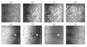 | Fig. 1- An example of 3D Flash Lidar image taken from an airborne vehicle. Image (a)-(h) is a sequence of 2D image planes taken from each different distances from the camera to the floor. Image (a) and (b) are mid-air, image (b)-(e) show parts of the water surface, and image (e)-(g) captured underwater and floor. |
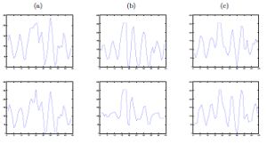 | Fig. 2- Example of the profile function pxy(z) in (1) for the airborne example in Figure 1. The graphs in the same column are taken from locations next to each other, which shows the similarities. When the profiles are compared against different columns, the differences are more noticeable. |
 | Fig. 3- Images (a) and (b) are a2 and a3: the frequency response of FFT applied to z-direction of 3D Flash Lidar image in Figure 1. They capture both the object and glints of the water. (c) The scalar image |
 | Fig. 4- (a) The result using two phase segmentation [1] on a scalar image |
 | Fig. 5- The top row are few images of a 3D Flash Lidar image showing a single object on the ground. Image (f)-(h) are a2, a3 and a4, respectively. Image (i) is a result using a scalar case of ¯u, using λ= 0.0001 and Image (j) is a result using a vectorial case of u = (a2, a3, a4), using vectorial model with λ = 0.0005. Using the vectorial model gives a cleaner result compared to the scalar case, since the vectorial model can be more stable against noise introduced from one of the images a2, a3 and a4. |